Machines that use multiple fans per system can monitor fan faults with a single signal that indicates when a fan is experiencing a fault. One method for doing is using a locked rotor output.
Tach (RPM) Monitoring vs Locked Rotor Output
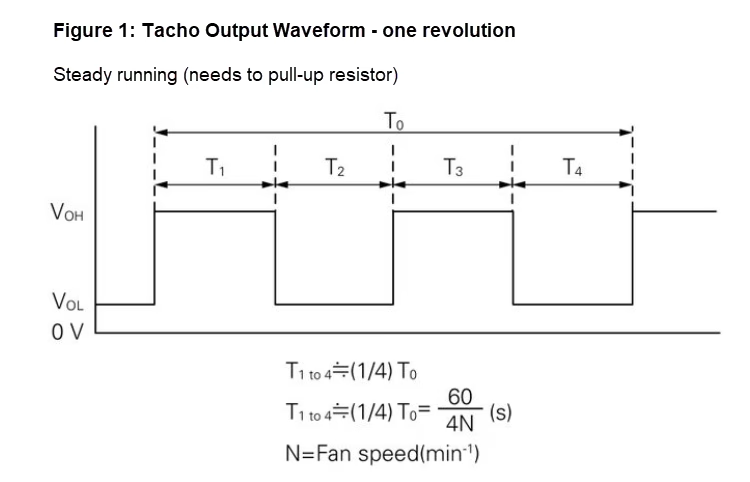
Some systems use a tachometer signal to watch each fan’s RPM, which allows you to track fan performance, spot wear and predict when a fan might need replacing.
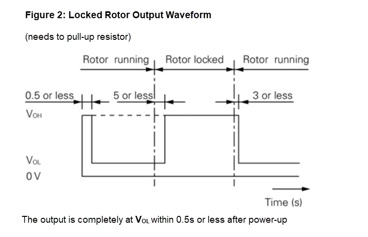
But in other designs, especially where there are many fans, engineers don’t need full speed data. Instead, they want a simple alert that only triggers when a fan stops moving. Locked‑rotor outputs provide that simple “fan‑stopped” signal without the complexity of RPM monitoring.
The diagrams below show the difference between the two signal types: a tacho output Figure 1 produces a repeating pulse that reflects the fan’s actual RPM, while a locked‑rotor signal Figure 2 only goes high when the fan stops turning.
Sources: SANYO DENKI AMERICA Blog
As shown in this diagram, once the fault is removed and the blade starts spinning, the locked rotor output goes back to its normal (low) state.
Combining Fan Fault Signals into One
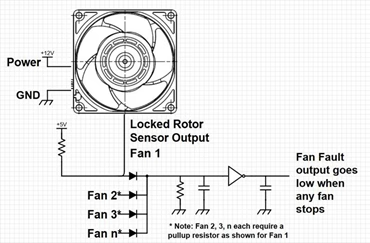
By using a basic Oring circuit made from standard parts like diodes, resistors, capacitors and an optional logical-level inverter, multiple fans can be monitored using one fault signal. If one fan fails, the system can activate its Over Temp Protection (OTP) to keep things safe. The image below demonstrated how the locked rotor output from each fan connects through a diode that carries out the Oring operation. If any of these fan fails, a master fault signal is created.
Source: SANYO DENKI AMERICA Blog
Please Note: Method Limitation
A locked rotor sensor output cannot identify which individual fan has failed, it can only produce an overall warning about a fan failure.
Choose the right solution with Motors and Fans. Find out more about our Sanyo Denki fans here and at motorsandfans.co.uk.